A few years ago, I encountered an issue in my project involving an I2C device that didn’t always work after a system reset.
In an ideal world, any reset should emulate a power-on reset, but we sometimes encounter warm start issues. The problem I was encountering certainly started feeling like a warm start problem, but I wasn’t sure what was going on. Are you sitting comfortably? Then I shall begin…
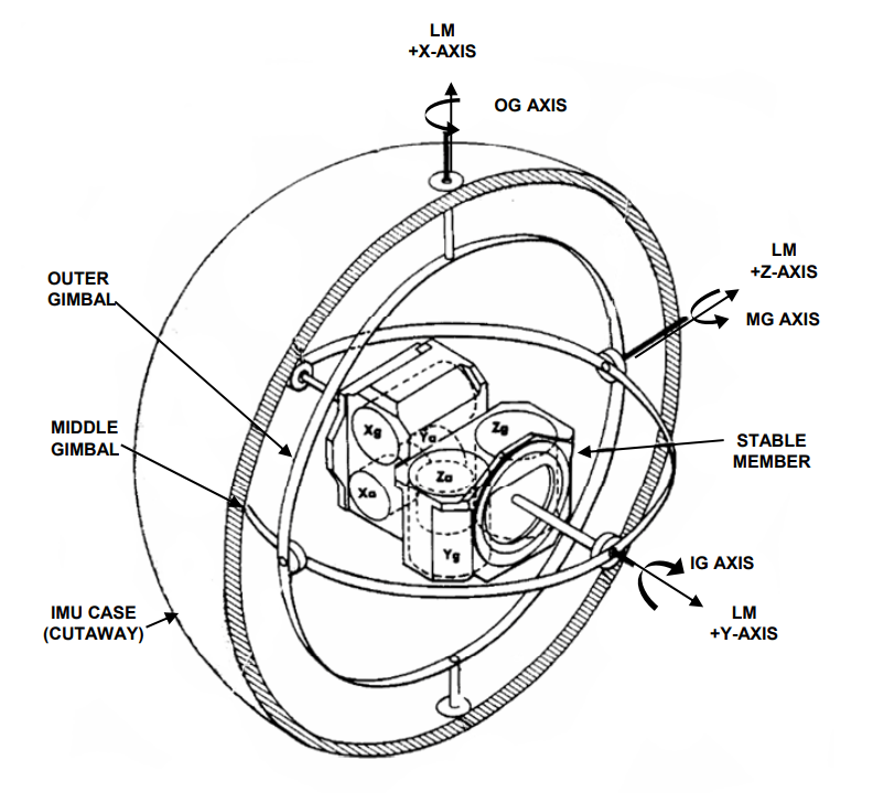
I was working on a nifty device that had a small ARM microcontroller (MCU) as the main controller, and amongst other things, an inertial measurement unit (IMU). We were still in the early stages of the design and hadn’t yet decided which bus to use for the IMU — I2C (inter-integrated circuit) or SPI (serial peripheral interface). The decision was coming down the line, and was based on all the usual trade-offs, like pin availability and what other devices were going to be on these two buses. The IMU was not the only peripheral. At that time it seemed that the I2C was the most likely option. I forget which 6-axis IMU it was, but it featured a gyro and an accelerometer. Both bus interfaces were available on the device, with bootstrap options to select the active one.
I was writing the driver code for the IMU device. The I2C was under hardware control. I think it was an Atmel (now part of Microchip) SAM G or its STMicroelectronics (ST) counterpart. Both Atmel and ST provide a library to interface to the I2C bus, so I’m not responsible for driving START, RESTART, STOP signals, address, or data transfer directly, I just request a bulk transfer in or out, and let magic happen several layers down. I’d spent a productive week or so incrementally adding code to query the device, and solicit single measurements. I was happy to see I could detect the orientation of the board by looking at the accelerometer results. After successfully querying the device manually, I transitioned to setting up interrupts for automatic periodic data updates from the IMU. It was about this time that I noticed a problem with my start up code. Roughly 10% of the time the IMU would become non-responsive after a system reset. A power cycle always brought it back to life.
I knew this was a software problem. My code was the only variable that had changed, so what had I done wrong? Using Atmel Studio’s debugger and the JTAG/SWD pod, I narrowed in on where my I2C transactions were failing. To my surprise, single stepping through the library, I discovered that the code failed to send a START signal. In twenty years of debugging I2C, I’d never seen that. The controller was actually waiting for serial data (SDA) and serial clock (SCL) to both be a logic high, signifying the bus IDLE state. That was where the code was sticking. Wasn’t there supposed to be a pull-up on this line? If the GPIO input was low, it meant that something had to be holding it low.
Initially, I believed the code was directly polling the serial data line (SDA) for a logic high, indicating a bus idle state. However, upon revisiting the Atmel application notes on the Two-Wire Serial Interface (TWI) controllers, specifically ‘AN2480 AVR315: Using TWI Module as I2C Master’, I realized a key detail. The software responsible for generating the START signal was actually requesting the TWI block to produce the START and then interrupt the MCU upon successful transmission. The issue lay in the TWI controller’s internal state machine, which was awaiting a bus IDLE condition that never occurred. This revelation indicated that the root cause was one layer deeper in the system than I initially thought.
That’s where I2C debugging switches mode. You’ve been focused on the code sequence, but when you encounter data in an unexpected state — early enough to implicate your init code — you realize it’s time for a change of approach. You walk through your code one more time, making sure you have set the pins as open drain. You now look at the schematic. “Are there external pull-ups, or should I be enabling the MCU’s internal weak pull-ups? Is that even an option?” When that all looks good, you have to ask “if this is going to pull up, who is driving it low?”
Note on Open Drain and Pull-Up Resistors:
I have mentioned open drain and pull-up a few times. For I2C, you don't drive highs and lows on the bus in the conventional sense. The I2C bus rests at a high level due to a pair of pull-up resistors. When a low is needed, the driving device, which can be the controller or the target, connects the bus line to ground, creating a low. This design allows both the controller and the target to control the bus without the risk of damaging each other. The result is a wired AND configuration: if any driver pulls the line low, the net result is low. The intricacies of GPIO drivers deserve a whole chapter in a book.
Since there were only two devices on my I2C bus — the IMU and the MCU — and we’d just reset, I concluded that the low state must be originating from the MCU. So, I dived into the Programmers Reference Manual, scoured the usual chapters on the TWI/I2C controller block, and double-checked my code. I also explored the GPIO configurations, which hardware block controls which pins. I wondered which interfaces were set up cleanly at T<sub>0</sub>, and which were “lazy initialized”, or set up just in time for power management. At that point I decided that peeking the relevant hardware control registers would be quicker than sifting through lines of code . This is where the vendor integrated development environment (IDE) shines over, say, GDB. The entire memory map was right there, and I could find the registers by name. You won’t believe what I discovered next.
Like me, right now you are reaching for a cup of tea, and thinking “this is bad”. Everything was correctly configured. All the muxes and control bits were set right. The data direction register was set appropriately for the SDA to be an un-driven input, and if we were driving it, then it would be high. The low was being driven by the IMU.
So, fresh out of reset, the IMU was holding SDA low. How could that be? Remember how I said this IMU, part of the InvenSense family, could be connected as I2C or SPI? I pulled out the user manual and the pin data sheet for the IMU to double-check the configuration options. I was specifically looking at how to select between I2C and SPI modes. As I scoured the pinout page and the diagrams to cross-reference with my schematic and board, I hoped to unravel why I was in such a big mess. And then, I found it. Or rather, I didn’t find it. There was no reset line to the IMU.
Being old school, I just knew as a universal truth that you need power, ground and reset. You may need a clock, but the other three you must have. It seems somewhere along the way gated power took the place of reset for small footprint, pin constrained peripherals. So I looked at the power to the IMU expecting to see it on a separate rail from the PMIC (Power Management Integrated Circuit), or gated through a FET (Field Effect Transistor) with board reset or power good gating it, or even a power mode control from my MCU that I’d not been paying attention to, after all, no one told me about board level power control of this device. I found it hard connected to system power. This little device had no reset at all! The only way to reinitialize was to toggle power. Since that was not under MCU control, then pulling the plug was the only recourse.
Let me back up. This little device did have a reset. You could send an I2C sequence to cause a few different levels of software-controlled reset. My problem was that the SDA line was driven by my IMU; I could not send a I2C message asking for an internal reset. How was I getting into such a state? I wasn’t quite ready to come up with a theory yet, and I was so much into a discovery mode that I didn’t think to Google it. It was definitely something to do with the MCU resets which I was driving each time I stopped my code, re-flashed the board, or restarted my test. So, I hooked up the scope, and decided to trigger off of SCL and see what my latest transaction was. Imagine my surprise to see that the last byte was less than nine clocks long (don’t forget ACK). I added a third signal, the one I should’ve triggered off originally, system reset. Yup, the reset was coming mid byte. Sometimes the IMU hung, sometimes it didn’t. Looking at the SDA was the last piece of the puzzle, the hangs were when we were in a read transaction and the output from the IMU was a zero bit.
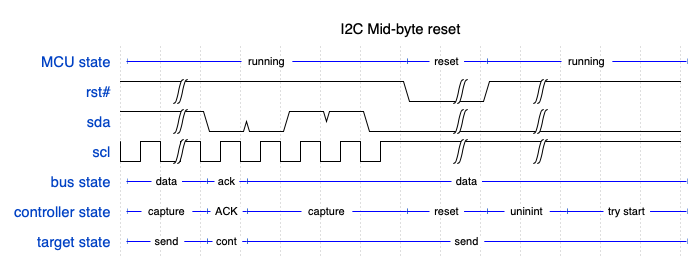
Now I could theorize about what was happening. The IMU uses a typical serial shifter to output data, and it knows to change the state of output on a falling edge of SCL. On the reset, the SCL was released by the MCU, and pulled up. The SDA from the IMU was held low. Without SCL toggling, there was no way for the IMU to complete shifting and consequently release the bus. Without a START we cannot move the IMU out of its send state. How do I get out of this?
The controller’s very smart I2C driver in the MCU knew that, first things first, we need a START. To generate a start we make a low-going edge on SDA while SCL is held high. The very smart I2C driver knew not to attempt this until the SDA is released to the high state. The target had clocked out several bits, and knew not to change the output until SCL went low again. The last bit is shifted out was a zero, so the IMU was holding SDA low. It was stuck. Then I had an idea. “What happens if I just clock a few more bits out?” Well, I toggled SCL once, and nothing happened. Clocking again, SDA went high at long last. A few clocks later the bus was looking like the IDLE state had been reached.
So there is my solution for you. Of course, you will not know how many bits into the byte you were when the system reset left your target device hung. You have to clock out a byte’s worth. That would be a minimum of 8 bits for data, and one for the acknowledgment cycle. It is important that the controller allows SDA to float as this is the signal to the target to stop sending a byte stream, it will be seen as a NACK. The definition of NACK in UM10204, section 3.1.6 says a NACK is sent when “A controller-receiver must signal the end of transfer to the target transmitter.” Adding a STOP after this might not hurt either. I didn’t do that, and I had no further issues.
We held a technical review after resolving this problem. I had a discussion with the board designer as to why and how this was a condition I could get the board into. Since we had the software accommodation of the hardware feature, we did not see a need to change the hardware. This was a low-cost consumer device. Since it was not “mission-critical”, we could accept having an FAQ saying “have you tried turning it off and on again” as a viable solution. The actual product did not expose the reset button, limiting exposure of the bug to watchdog-resets. With the software accommodation we were ready to ship.
Since this incident, I have made it my policy to
- champion for proper reset trees where possible.
- champion appropriate power trees for both clean power-up sequence and power consumption reduction. always clock SCL 10 times before I start an I2C bus (in single controller scenarios).
I hope you can learn from my adventure. May you enjoy many miles with your I2C bus.
Image credits
- By NASA – Apollo Guidance, Navigation, and Control (GNC) Hardware Overview, https://ntrs.nasa.gov/archive/nasa/casi.ntrs.nasa.gov/20090016290.pdf, Public Domain, https://commons.wikimedia.org/w/index.php?curid=73554893
- Waveforms created by author using WaveDrom https://wavedrom.com/editor.html

One thought on “An adventure in debugging an I2C bus hang”