Reading datasheets is hard
- What is the problem?
- So why do we get problems?
- Description on the schematic
- Description in the datasheet
- Using the address – APIs can’t decide if it’s 7 or 8 bits.
- Making things better?
- Last words
What is the problem?
In my 30 years of experience, I’ve seen at least one instance every year where someone gets the addressing wrong on an I2C target device, which has a 7-bit address. It’s a simple process, really – addressing a device for read or write transactions. Typically, with experienced team members on hand, these issues are resolved quickly. However, occasionally, an engineer, confident in the simplicity, spends too long trying to fix it alone before admitting they’re stumped.
The I2C (inter-integrated circuit) bus is prevalent in embedded systems. While there are other buses for communication between components on a circuit board, I’d say about 70% of the systems I’ve worked with included I2C. Every time we added an I2C device to a board, invariably, someone would mess up the address.
The I2C peripherals I have encountered include
- IMU (6-axis, 9axis)
- image sensor
- EEPROM
- flash
- custom logic in CPLD or FPGA
- LED controller
- PMIC
- CAC (crypto authentication chip)
- MCU as target
- DIMM SPD
Okay, there is a bit more complexity to I2C addresses than just a 7-bit address and a bit known as R/W# ( read – active high, write – active low). Some of the other concerns are
- 10 bit addresses
- There are some devices with 10 bit addressing. I have not met one in the field yet.
- SW configured
- An MCU with an I2C target block may have a SW configured device address.
- OTP (one time programmable) or NVMEM (non-volatile) configurable address
- Devices may have software-settable device addresses.
- Microchip ATECC608B
- HW address select pins
- some devices have several address select lines.
- The TI TCA9548A Low-Voltage8-Channel I2CSwitchWithReset has A0-A2, three select lines, so the address can be any from 0x70 through 0x77
- I2C mux/bus expander
- a multiplexer that will select one of several I2C busses that the controller can interface to
- Chain through devices
- For example, some IMU devices can take an external magnetometer, which can either be controlled by the IMU, or using the pass through mode, the host controller can manage directly
- Multiple I2C targets in one package
- You may have a device like an 9 axis IMU with a barometric pressure sensor. This may actually be several dies in one package, and the sub-components are individually addressed
As I say, it’s never easy, someone on the team always goofs up somewhere on a new board.
So why do we get problems?
Taking the simplest 7-bit addresses, not SW changeable, no chaining or mxing, we still hit two fundamental problems.
- Description – How the address is specified
- Usage – How the software expects the address.
Description on the schematic
There is no obligation for the board designer to annotate the schematic with the I2C address of a device placed on the board. When the designer does include this detail it may not be in an intuitive location, such as
- adjacent to the peripheral
- tabulated on the same page as the peripheral
- interconnects page
- last page
- rely on datasheet
The designer will use one of two formats for an I2C address
- 7-bit address
- 8-bit combined address + read write
- Write address – always an even number
- Read address – always an odd number (write addr + 1)
Whatever is on the schematic may be wrong if a drop-in replacement that is pin-compatible, but not address-compatible is used on your final board. Even if it’s only during schematic review, you will be checking the address in the datasheet.
Description in the datasheet
Composing the address
This is where things get really fun. Just looking at several vendor datasheets and user guides, we can see that the address is not always obvious. The first challenge is finding this information within the datasheet or user guide. You will typically be looking at a PDF, either with your browser for a quick reference, or you downloaded and use a reader, like Adobe Acrobat Reader, which offers a richer experience of search, bookmarks and contents tables. You might be one of those people who still print and mark up the document.
Looking for the address needs the right search term. Adobe Acrobat Reader (free version) does not allow wild card searches. Let’s start with searching for “address”. This can be an issue when the target device is providing a register file interface, and the term “address” is repeated several dozen times when defining the internal memory map. If you are not familiar with devices like that, then this result in your search may confuse you. From a Kionix datasheet I found this table. These are not the address values to be sent in the first byte of your transfer.

The next search term to look for is the “i2c address”. This is where you want a wildcard or regex “i2c .*address” will hit on “i2c slave address”, “i2c device address” or the more modern “i2c target address”. The results you will get are quite diverse. A Bosch datasheet yielded text and a tabulated form

That’s pretty decent. The text is a little clunky, but matching the text and table, it’s clear we are talking about 7-bit addresses, even though the table is not labelled as suc
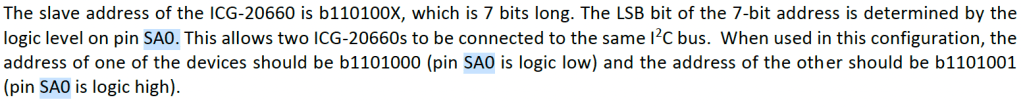
InvenSense does an okay job of presenting at presenting the 7-bit address in this following paragraph. There was no pretty table, and note also that the address is only presented in the binary. I guess binary only is better for matching the bit pattern on the scope when you are debugging, you won’t keep thinking of it as 0x68 or 0x69, and forget to mentally shift by one. Here you see “slave address” would be a better search term, and you can see that I had searched by a pin I’d seen on the pinout page, SA0, selecting the LSB of the address.
Now, I have another InvenSense datasheet, this one for the ICM-20789 IMU with pressure sensor. This device is a complex little SoC. There are two I2C interfaces, you can talk to the pressure sensor directly, or cascade through the IMUs internal I2C controller. We are not here to discuss that, but look at how the address is presented (hint: behavior changes with “bypass enable”). Searching for I2C device address I get the information for the pressure sensor, but not the main IMU device. This is still InvenSense, but a different product family, and a different style.

This is lovely, an unambiguous address. See how the binary has the tick between bits 4 and 3, breaking up the 7 bits into readable chunks, like we add commas to numbers over 10,000. There is the decimal and hex value for us to use as well. Now if I search the same document for “I2C address" I get the address for the IMU. This is presented like the previous IMU in the definition of the Digital Interface.

Even though this IMU and the pressure sensor are in the same datasheet, you can see different format for the binary numbers, and one interface is in binary only, while the other has binary, hexadecimal and decimal representations. The documentation seems to be two or more datasheets for separate components bound into one volume, much as the overall IC is multiple die in one package.
For the Fairchild FIS1100 there are only 5 search results for “I2C” in the datasheet, and this is the wording for the address. Would you search for “i2c slave device address”?

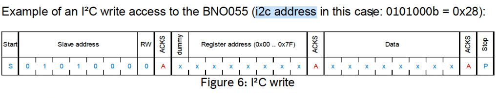
This snippet from the Kionix KMX61 datasheet shows how the LSB of the address is set. They show the 7-bit address and the 8-bit value we need to send in our first byte after START. It perpetuates the legend of a read address and a write address, which other datasheets either never mentioned, or only alluded to.
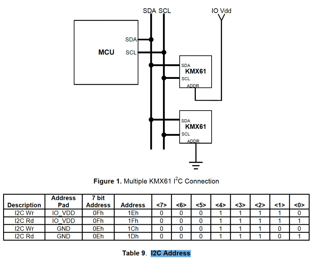
I found an ST component that has two blocks, each with their own I2C address. One of the two has a selecteble LSB. The two interface definitions follow the same format; If we grab the well-worn printout from our desk, we may scan through the pages until we see the table we think we are looking for, and not realise it’s the wrong one. When we do find the right one, we find that we are being presented with an 8-bit address, not a 7-bit. It’s not immediately apparent that is what they are presenting. It would be very easy to accidentally do one more shift and OR to the values presented here.

The second interface is presented in the same format, but does not have a configurable address.

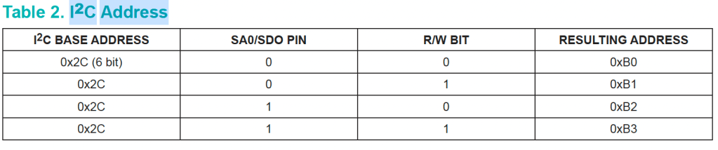
Maxim, in the MAX21100 datasheet, also presents us with the 8-bit address. There is no “6-bit base address” defined in the I2C specification, and I wish this table had represented those upper bits as bits[6:1].
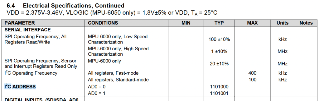
One last weird one, I found this in an InvenSense datasheet. The address was actually defined in the Electrical Specification, rather than in the I2C operation, or Digital Interface section of the document. It wasn’t defined exclusively in this table, but this was the only match for the search term “i2c address”.
So there you have it, out there in the field we are trying to pluck familiar information from a variety of formats. The chip vendors cannot agree on the most fundamental ways of presenting the information.
- 7-bit vs 8-bit
- There is a divide over whether we are using 7-bit or 8-bit addresses. It’s often explicit which format they used, but sometimes it is not. For convenience, some vendors provide both.
- Binary or hex
- There is no consensus over hex versus binary. I’m not sure why anyone would use decimal as it obfuscates any simple bit patterns.
- Least significant bit(s)
- Even if you comprehend your datasheet, the information is incomplete if you have a choice of addresses. You will have to refer back to the schematic to see which of the options was selected.
Bit number vs clock cycle count
Often you will see a section of a devices user guide that will tell you all you need to know about I2C to interface to this one component. There are two different styles in presenting this information, one is to talk in clock cycles, the other in bit numbers. I2C addressing is sent MSB (most significant bit) first.
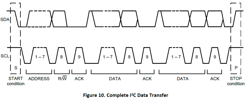
The below timing diagram shows the nine clock cycles counting 1-9. This does not imply the bit order is LSB first.
This timing diagram however shows the bit ordering, rather than the clock count.

Using the address – APIs can’t decide if it’s 7 or 8 bits.
So after seeing how not all datasheets define the addresses the same, with a mix of 7-bit and 8-bit values, presented in hex, binary, and even decimal, you can see how easy it is to misread the datasheet. The board designer would use the same mixed representations too. The poor software engineer has to think about what number they are reading. At least once we get the 7-bit address and the Read/Write# flag we are ready to use that in the API.
Life’s not that easy. Some libraries, use the 8-bit AD+W addresses and a block transfer, and some use the 7-bit address with distinct read and write commands.
A 7-bit addressed SW interface.
The Wire library for Arduino provides control of TWI/I2C interfacing.
https://www.arduino.cc/reference/en/language/functions/communication/wire/
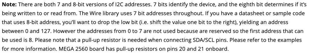
When we look at the introductory text they talk of the 7-bit address. The commands provided will open a logical connection to a device with a 7-bit address, and then the transfer commands will handle the assembly of the first byte to include the address shifted and the read flag set in bit 0 of the transmit byte.
An 8-bit addressed SW interface.
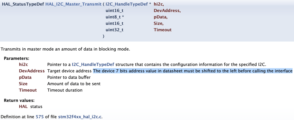
ST provides an API for I2C that relies on a core byte shift function, as a result, it is up to the user to compose the 8-bit value to send in the first byte. The instructions tell you that you MUST shift the value in the datasheet, but we have already seen that some datasheets already provide the 8-bit value.
Making things better?
I2C addressing is hard. It’s not impossible to navigate the problems, but it’s a subject that is not kind to those new to the game. What can be done to improve the situation?
Internal documentation standard
Being aware of the confusion in presentation styles and two basic flavors of API is a big step towards an easier life. Having a common language between the hardware and software teams helps too. Look for introducing a standard to use at your place of work. Every company you work at may have a different idea what this should be, but pick one, are you going to express everything as 7-bit addresses in binary, are you going to commit to 8-bit and hex. It doesn’t matter what you choose, but reduce ambiguity within your organization.
Schematic considerations
Champion for good documentation on the schematic. In small start-ups and agile teams, there seem to be missing documents specifying how a board should be used, with a well-annotated schematic you can sidestep other formal documentation. Make sure the software engineers get involved in some level of schematic review, call them in to review how an I2C target component interfaces to the host controller. They will let you know if they have the information needed. You may use one central table to show all addresses on the I2C bus (or busses), or you may place the address next to the component. Pick a style and be consistent.
Add I2C addresses to the silkscreen layer of prototype boards. If you have the board real-estate for this, it becomes invaluable. This is especially useful if device addresses are re-mapped on later iterations of the board, or sibling product use different addressing. As you progress through the design process, developers will have a collection of boards and schematics to juggle, and keep matched. How many times have you gotten the wrong schematic, and took some time to notice your mistake?
Software Specification
Software engineers should make themselves a cheat sheet for the device they are working with, something simple that will show you the 7-bit and 8-bit addresses in hex and binary, with any jumper setting for addresses that are still in flux. This sheet will help you when converting between datasheet, schematic, and API documentation, and also, the binary becomes crucial when you start looking at traces on the oscilloscope. You can also keep other notes in the table.
| 7-bit | 8-bit | notes | |
| IMU read | b001_1000, 0x18, r-1 | b0011_0001, 0x31 | SA0 tied low |
| IMU write | b001_1000, 0x18, r-0 | b0011_0000, 0x30 | |
| EEPROM read | b010_0100, 0x24, r-1 | b0100_1001, 0x49 | |
| EEPROM write | b010_0100, 0x24, r-0 | b0100_1000, 0x48 | WP on GPIO 15 is active high |
If you are developing an API to handle I2C transactions, make it very obvious in your API documentation what you expect. The closer you get to the metal, using a TWI or I2C controller, especially with DMA, you will be using the 8-bit value to align code with hardware. If you are bit banging, you may implement separate send data byte and send address byte functions, and be happy with 7-bit addressing. I like the Arduino upper level API though, it wants the 7-bit address from the user, but this may go against the style of other libraries your company has already developed.
Last words
If someone is struggling with I2C addressing, remember your first forays into this realm and be patient. Always read the documentation carefully, and never assume that the style is consistent even within a single user guide or datasheet. Try to be consistent and clear in the documentation you create.
I2C is fun, I hope you enjoy the adventure.
