Life is a continuous learning experience. I have been using RS485 for about 20 years, on and off. Despite all that experience, I found something new for my toolkit a few months ago.
I suspect some of my audience has been using the same RS485 solution for decades. There will be a similar portion who did their first RS485 hobbyist project in the last couple of years with a cheap module from SparkFun, Element14, or some other such catalog. I suspect the second audience does not even know of the troubles we old-timers used to face.
Don’t worry if you are not in either group, I’ll give you the top-level details so you’re not completely lost. RS485 is an electrical specification for communications wiring in factory settings and stage settings such as film studios, theaters, nightclubs, and rock concerts.
RS485 Intro
Much of the life of an embedded software engineer is spent moving data between very small devices. Yes, we also process the data in various ways, and then that information is used to control something or has to be moved elsewhere.
One way of moving data is through a serial port. That is a connection that sends data one bit at a time sequentially. The UART (Universal Asynchronous Receiver Transmitter) is a common serial port. It wiggles voltage levels in a specific way to move the data.
Across a circuit board, serial buses use logic-level voltages. Historically we would see 5.0V logic, later 3.3V, then 1.8V, and now we are around 1.0V. If you are sending signals between boards or systems, then RS232 levels are used (about +10V to -10V). You simply add a charge pump to achieve this.
In an industrial setting, there is often too much interference on longer cable runs; a more appropriate electrical specification would be RS422, which adds differential signaling. Like RS232, RS422 supports full duplex communications point-to-point. These are EE issues for the most part. The only reason an embedded softy needs to know is so they can grab the right test equipment to monitor the system when things go wrong.
There is an alternative to RS232 and RS422; you can use RS485. RS485 supports half-duplex messaging, allowing point-to-multipoint messaging with responses solicited from the nodes. RS485 is popular for industrial control systems. This reduces cable complexity at the cost of lower data throughput and more code complexity.
The Traditional RS485 Transceiver
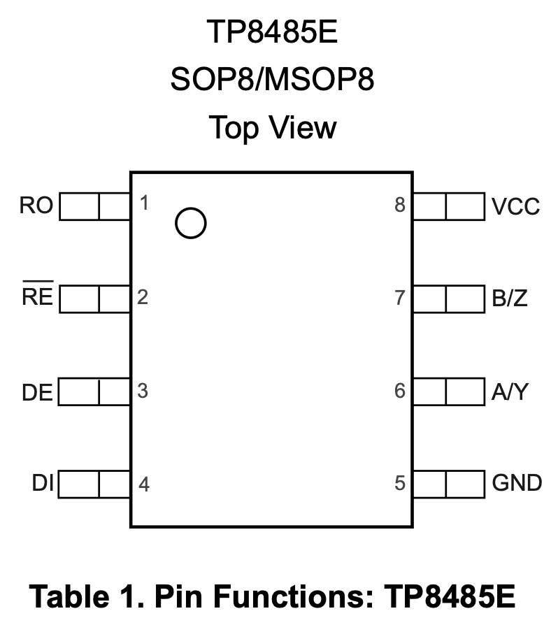
If you look for RS485 transceivers online you will find a vast selection. TI, Analog Devices, Maxim all make them. I went to Digikey and found a brand I’d not seen before, 3Peak; the above is their TP845E, one of a family of 8-pin ICs.
The left side of the chip is all facing the host processor, typically an MCU. The pins are:
- Receiver Output (RO)
- UART level RX data to MCU
- Sometimes called R, RX
- Receiver Enable# (RE#)
- Logic level, active low control of receiver buffer.
- Sometime called RXEn#
- Driver Enable (DE)
- Logic level, active high control of transmit buffer.
- Sometimes called TXEn
- Driver Input (DI)
- UART level TX data from MCU
- Sometimes called D, TX
On the right, we have power and the data bus:
- VCC
- Positive power
- B/Z
- one half of differential signal
- A/Y
- complimentary differential signal
- GND
- Ground
Typically in the datasheet you will have either a functional equivalent diagram, or a truth table to show how these all relate. For a transceiver, I prefer the functional diagram. This one is borrowed from TI’s app note SLLA574 RS-485: What is Auto-Direction and Why it is Useful in Systems?

And yes, that app note is what we are talking about here today.
We said before that UARTs are full-duplex. They have a receiver and transmitter that are independent of each other. We can have the receiver always on, and anything seen at A and B will also be present at R (RO) and, therefore, received by the MCU.
We also know that RS485 supports point-to-multipoint or multi-drop bus topographies. Any node can become the transmitter. If we have more than one node on the bus transmitting, then we get conflicts when they drive different values.
To prevent conflicts, only one device at a time is permitted to transmit. A higher-level protocol determines who can talk and when. There is normally a leader/follower or controller/target scheme with a mix of broadcast and poll/response messaging.
Unless it’s your time to transmit, you disable your transmit driver.
Unless you are monitoring your transmission for conflicts, you do not need to receive the data you are transmitting. You will see that transmit enable and receive enable are opposite states in most transceivers, and the MCU can use a single GPIO for RE/DE#. Before sending a burst, the MCU must enable the transceiver driver, and after the last bit has clocked out of the UART shifter, release the bus.
This might not sound like a big problem, but it does mean that in the low level TX ISR we have to manage the transceiver enables.
That’s definitely straying into the world of embedded. In software you use a write function (puts(), print(), etc) to send an array of bytes to the serial port. Under the hood, the data is copied into a transmit buffer, and then a DMA engine or interrupt handlers have to service the UART on a byte-by-byte level. Before the first send, we have to enable the transceiver’s driver. After the last data has been sent by the UART, a final call to the interrupt handler will clear the transmit enable and restore receive enable.
If only we could avoid that complexity!
Some of you will now say “but Alex, we can use glue logic for that.” This example from a Renesas App Note shows one solution used on a J1708 bus rather than an RS485 bus.
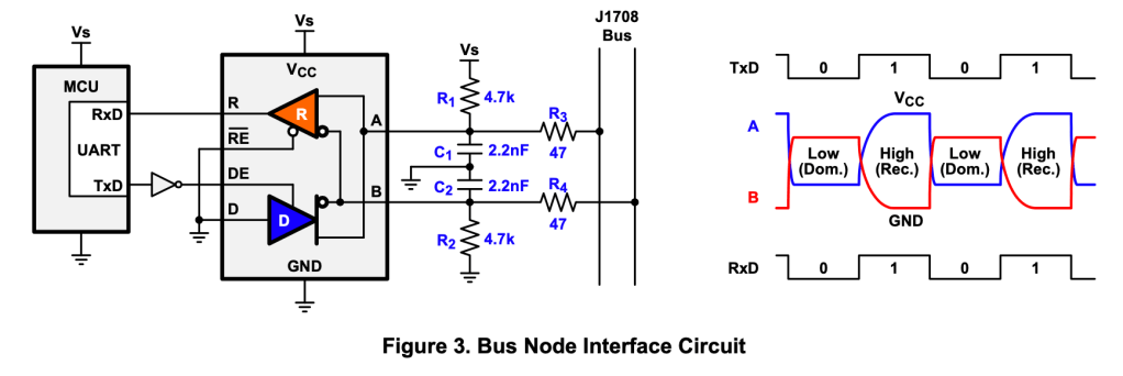
I’m not a big fan, but yes, it does the job. As the driver releases the bus, the pull-up/down resistor returns the bus to the other state, I fear slower rise times.
Hobbyist RS485 Line Driver Modules
I needed to breadboard some RS485 solutions. There seem to be a large number of similar modules out there matching the traditional 8 pin chip. Then I started finding module which presented a simpler interface to the MCU
- TX
- RX
So, I had a look at a few to see what fancy glue logic they were using to do this.
Several of them were trying tricks to infer the intent to transmit from the state of the TX line from the MCU. UART lines are held high when idle, whenever TX is low, the modules would drive a zero state to the A/B line. Whatever logic is used for this is done for us on the module. It might not yield best performance at all speeds, but seems an adequate solution for prototyping.
Then I found a different solution; the transceiver had built-in auto-direction logic.

The MAX13487E is a good example of such a device. All the glue logic is embedded in a state machine.
The state machine not only uses combinatorial logic for driver enables derived from TI but also brings in the output of the RX buffer. This allows it to suppress transmission if the bus was not idle. The state machine is tabulated below:
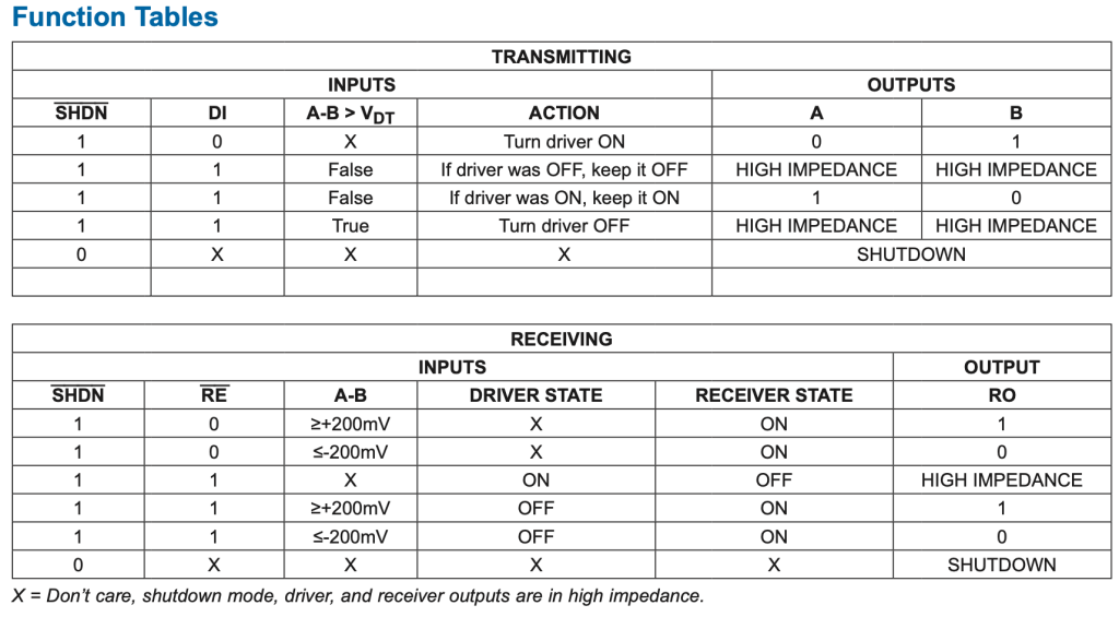
The driver push-pull will give clean transitions between the two states, however, when DI return to high, the driver is only momentarily driven to the state, then the driver is disabled to allow other bus drivers. A pair of pullup, pulldown resistors are needed to hold the bus in this state.
Isn’t that wonderful? If I’m coding for the leader, all I need do is wait an appropriate time for a response after a poll. As a follower, speak when spoken to. I can use the UART drivers that come in my MCUs SDK, and not have to modify them for RS485 enable lines.
I found information for my EE buddies, too. Analog Devices have a design note, DS96 Simplify your industrial interface by eliminating RS485 control lines. RS485 often is in a harsh environment, and you may want to isolate your RS485 transceiver from your MCU. Now, you can buy an expensive RS485 transceiver that has built-in isolation, but you could also put an opto-isolator between your MCU and your transceiver. If we had full control of our transceiver, that’s four signals to isolate. With auto direction, we only need two, potentially looking at freeing up board real-estate, or reducing BoM costs.
There are other auto-direction transceivers from other vendors. They all bring variations on this theme. They have their own personalities with regard to timing parameters and collision prevention. Make sure you pick a device that suits your requirements.
Do I Need This?
One past problem that I see this solving with apparent ease is a problem I faced a couple of years ago. We had a small ST micro hanging out on an RS485 bus. Those of you familiar with these ST parts know that the internal bootloaders provide an easy mechanism for in-circuit field updates of firmware. They have DFU on USB ports and similar interfaces on the UART, I2C, and SPI ports. See AN2606 at www.st.com for full details.
The UART interface is only TX/RX with no notion of an enable for an RS485 transceiver. We’d implemented a classic port, with TXen/RXen# wired together to a single GPIO. We felt we could not leverage the internal bootloader for firmware updates, so we implemented our own protocol to buffer, or rather stage, then flash a new image. This took weeks to implement, building both the transfer engine and the reflash tool rather than leveraging existing sample code and canned functionality.
I’d love to talk with my old team about this. There was enough complexity in that system that I know we would have had other challenges, like parking the peer nodes during the FW update.
Wrapping Up
There you have it, a whole new class of devices to look into. I hope you find one that suits your needs.
Are there any times when you would have benefitted from using an autodirection transceiver in RS485? Have you had analogous problems on other buses and found comparable solutions? Do you have a favorite clustering of glue logic to implement this in hardware? If so, does it break down at certain data rates?
I look forward to hearing about your adventures and reading your comments and suggestions.
