
Off-by-one is a frequently occurring software problem. It’s where we iterate one time too many or too few. If you go too far you corrupt data in memory beyond the array you are manipulating. If you stop iterating too soon or start too late, then the end value never gets dealt with.
Every now and again, we have to roll up our sleeves and add BIST (built in self test) or Factory Test Code. Today, I managed to get a production line yield of 0% when testing an LED matrix. The visual inspection failed because the last pair of columns seemed shorted to the same control line.
Okay, so it was a production run of 1 unit, or rather, it was me writing my line-end acceptance test using an early prototype as my DUT (device under test).
This is a tale of a typical day’s embedded debugging. I hope you are up for some technical details as we will be going deep into a single simple instruction. You may find the information helpful. At the very least, the next time you have a non-technical manager asking you why your code isn’t working yet, send them to this page, and they’ll see why coding schedules can be so unpredictable. I only lost two hours overall, but have enough of these in a week, and you lose a day.
Contents
- Contents
- The Product
- A Simple Test
- A Simple Failure
- Finding Fault
- LED 19 – An Off-By-One Bug
- A Lot Of Negativity
- What Does “<<” Actually Mean?
- Implicit Casting, Type Conversion, Sign Extension (The Perils Of C)
- Summing Up The Debugging
- The Background Information You Are Missing
- My Solution
- Lessons I Learned While Writing This Post
- Wrapping Up
- End Notes
The Product
As part of my life in a tiny start-up, we need to keep the lights on while working on the white papers, patents, elevator pitches, and the search for finance and market. To pay the bills, we have a few clients we provide engineering services for.
One client needs a controller board, and part of that system is an LED character array. The rest of the product includes control over an EIA-485 link, a DIP switch, some environment sensing, and an engineering interface. This is all handled by a small MCU with SPI and UART interface controllers onboard.
As you can imagine, we want to make sure all the dots in the matrix light up properly before we ship the device, so we need a factory acceptance test. We get more value from this sort of test if it can later double as a field service check, started via an engineering interface. When repairing a unit that failed in the field, such diagnostics can be invaluable in identifying problems and verifying fixes.
A Simple Test
The LED driver chip we are using (LP586x) provides some level of BIST, showing if any LED is open or shorted.
An open will be reported for a failed diode, missing diode, open (cracked) trace, or unsoldered pin. Open detection can be done by simply turning on all the LEDs for a minimum duration, and the BIST will capture the information.
A short will be reported if the diode’s anode and cathode are shorted. To make sure I see if adjacent dots are shorted, I need to drive them one at a time.
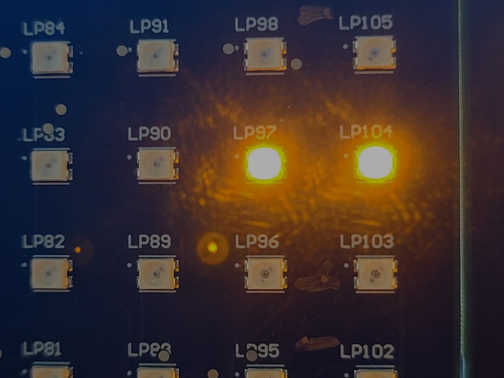
A visual inspection is very valuable to check for shorts, with adjacent LEDs lit, or ghosting, where rows of columns will glow together. The operator has to see every dot lit individually to ensure correct behavior.
Ghosting is an artifact of how the LED driver works. We are using an LP586x from TI, which has 8 line selects and 18 current sinks to drive 144 LEDs by scanning. You can imagine how critical timing is to make sure any capacitance on one node is discharged before the next is driven.
So, given the parameters, why not write a walking-ones test? It’s the classic. Its complement is the walking-zeros test, which I think I don’t need.
void walking_ones(uint8_t cs, uint16_t delay, uint8_t show_activity)
{
	uint8_t row, col;
	uint32_t bit_pattern = 0;
	if (show_activity)
	{
		console_SendStr("Walking Ones Test\r\n");
	}

	for (row = 0; row < 7; row++)
	{
		if (show_activity)
		{
			console_CRLF();
			console_SendStr("dots: ");
		}
		for (col = 0; col <= COL_PER_CHIP; col++)
		{
			if (show_activity)
			{
				console_SendChar('*');
			}

			bit_pattern = 1 << col;
			console_SendNum(bit_pattern); // test print
			write_line_dots(cs, row, bit_pattern);
			delay_ms(delay);
		}
	}
}
A Simple Failure
I ran the test, and as I saw shorts, I inked up my board with a gold Sharpie. It shows up nice on black solder masks. After three rows, I saw that the last pair were always shorted! This is the test walking horizontally: LP90, LP97, and LP104.

I had said before that this was my proto-board, and I had instrumented up the LED driver. I assumed I had a solder splash (I’m a firmware guy, not an EE or technician; my soldering is merely “okay”). The tacked-on test wires had been potted in hot glue. To make matters worse, I had run temperature tests, and so the component still had thermal compound on it. I was using a probe, not a FLIR, for measuring how hot it was.
I’d been running other code on the board and didn’t remember any issues with individual LED control. Two columns together felt like a strange HW bug and impossible with my code. I told my EE what I saw and told him I wasn’t going to worry about it as a design issue or code issue. I had other fish to fry and moved on to the more pressing tasks.
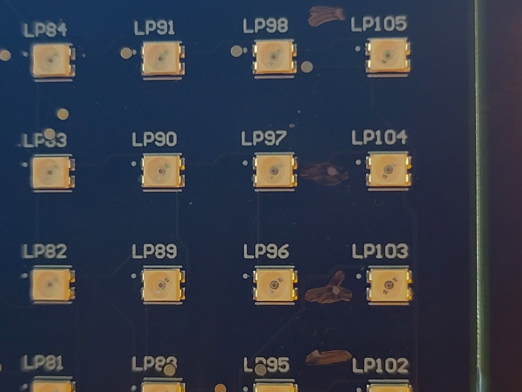
I came back to the issue a couple of days later when I finally had bandwidth. With a plastic spudger, I managed to remove the hot glue. A KimWipe and isopropanol (alcohol) took care of the thermal compound. There were no obvious board issues. Of course, the LP586x has a BGA (ball grid array) package, so I couldn’t see everything that was happening regarding package to PCB connections.
Next, I ran the code and watched the sequence again. This board variant does not use all 18 LEDs in a line; it uses three groups of 5 for 5×7 characters rather than a contiguous 18×7 graphic array. LEDs 6, 12, and 18 are not populated. The walking-ones test actually scans everything, so we can use it for both the character display and the graphic display.
I was used to a phantom LED at the end of the row being driven, giving a delay between each row. For my convenience, I give each LED one second on time. I realized that the double dot was only on one second, not two, and the blank was two seconds. If the two columns were shorted, then we should have had 2 seconds on-time for that pair. I knew now that my simple walking-ones code was at fault.
Finding Fault
One thing that confounds firmware engineers all the time is numbering. How hard can numbering be?
Register bits and IO pins on our MCUs are zero-based. If you have N items, the first is 0, the last N-1.
However, for hardware, items like pins on a connector or LEDs, switches, motors, and such on a board, we count ones-based. The first is 1, the Nth is N.
These two different counting systems can lead to confusion within the software. It’s a straightforward mapping, but once in a while, we mess up.
The failing LEDs were in columns 16 and 17 shorted, but then also column 17 was a no-show on its own. This means bits 15 and 16 had issues.
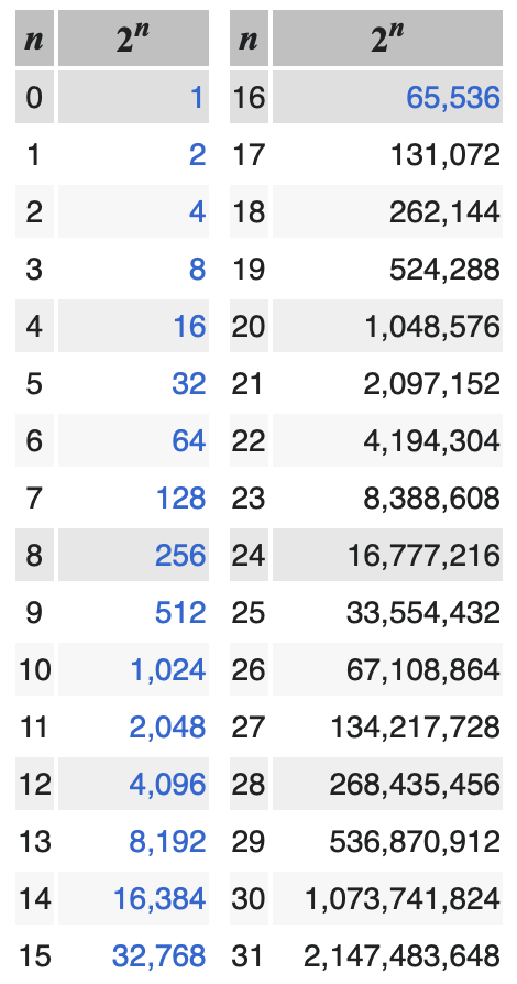
I think that was when I got my next clue. 15 and 16 are significant numbers when looking at bit positions. Bit-15 is the top of a 16-bit data type. Bit-16 would be the start of the second 16 in a 32-bit type.
Since there was a delay in the loop, single stepping I knew would be painful, so I dropped in a print to confirm my suspicions. Normally, I would print hex or binary to see the walking bit, but I am running lightweight bare metal code and don’t have printf or sprintf to help me; these are “formatted print” functions. I had to print the decimal. Though a small footprint system, I did have room for a print that I would later remove.
Walking Ones Test

dots: *1*2*4*8*16*32*64*128*256*512*1024*2048*4096*8192*16384*-32768*0*0*0
dots: *1*2*4*8*16*32*64*128*256*512*1024*2048*4096*8192*16384*-32768*0*0*0
So, we expect to see a doubling every time we shift the bit representing the LED.
| LED# | bit position | expected (2^n) | observed |
| 1 | 0 | 1 | 1 |
| 2 | 1 | 2 | 2 |
| … | … | … | … |
| 15 | 14 | 16,384 | 16384 |
| 16 | 15 | 32,768 | -32768 |
| 17 | 16 | 65,536 | 0 |
| 18 | 17 | 13,1072 | 0 |
| 18 | 262,144 | 0 |
So, everything was normal up to LED 16, then things went quite strange:
- LED 16 – suddenly negative
- LED 17 – suddenly zero
- LED 18 – still zero
- LED 19 – I never wrote to 19, but it’s in the log messages
LED 19 – An Off-By-One Bug
LED 19 is easy; that is a classic off-by-one.
for (col = 0; col <= COL_PER_CHIP; col++)
This was possibly a result of changing number-spaces from internal to external. It might also be CAPE (copy and paste error). Or I could have relied on CoPilot’s line completion. Yes, I have CoPilot from GitHub running in VS Code for my primary editor. It’s a careless mistake.
Some of my code, when bounds checking user input, is working in the range [1..COL_PER_CHIP]. However, when I’m working on the driver code for the LED driver chip, I work with [0..COL_PER_CHIP[ or, to express that another way `[0..(COL_PER_CHIP-1)].
So, for my “every column” loop I need a less than test, not a less than or equal to test.
for (col = 0; col < COL_PER_CHIP; col++)
A Lot Of Negativity
Let’s look at the bit-15 issue. We have the correct magnitude but in the wrong direction.
Negative numbers are represented as a two’s complement. Basically, you will expect a lot of ones in the upper bits of a negative value, and always, the most significant bit will be a 1. Where did all those ones come from?
The bit pattern for col 15, that is, only bit-14 set, should be 0x0000_4000. After the shift, we should have 0x0000_8000 (32,768); what we were getting was 0xffff_8000 (-32,768).
I know I said I wasn’t going to single-step, but that was when I realized this was a learning point, and I decided to blog about it. So here we are with our last good value. I now regret capturing in binary; I thought it would be easier for you to see, but it’s hard counting all those zeros and ones.


The critical line of code can only be one line. But it’s so fundamental, what can the problem be?
bit_pattern = 1 << col;
What Does “<<” Actually Mean?
The << operator means logical shift left. That is, move every bit in a memory location one bit to the left. If anything falls off the left, that’s fine. The rightmost bit becomes a zero. This is actually the same as an unsigned integer (or fixed point) multiply by two; that’s why our values seem to double. There are arithmetic shifts, which can work with signed integers.
I stepped into the << function, yes it’s not just an assembly language LSL instruction, there is more to it.
void _ILSL(char j, ...) { /*lint !e579 the function contains inline assembly only (no invocation of va_ macros) */
/* DESC:    16 bit shift left k = i << j
   IN:      X:A i, TOS j
   OUT:     X:A k
   WRITTEN: A,X */

  asm {
                TST j
                BEQ  _ILSL_2
  _ILSL_1:
                LSLA
                ROLX
                DBNZ j,_ILSL_1
  _ILSL_2:
  }
}
That’s one heck of a shift, isn’t it?
What you are looking at here is the assembly code of how the shift is implemented. I’m out of practice at this stuff, but it confirms my concerns. That’s a 16-bit shift operation. Look back at my code and debugger output; you’ll see we have a uint32_t that we are manipulating. That is a problem.
You will also see two operations. Remember I say this was a small MCU, it’s actually an 8-bit micro.
Let’s see how an 8-bit micro can do this 16-bit shift. Then, we will see if we can make a 32-bit shift somehow.
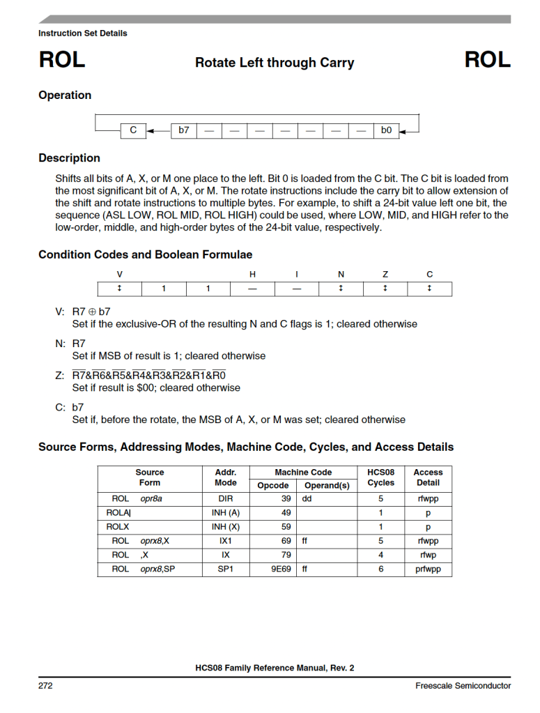
Let’s decode that line by line. If you want to play along at home, the instruction set manual is http://uprt.vscht.cz/souskova/soubory/REFERENCE_MANUAL-HCS08.pdf.
TST (test) will set the flags based on what we know about j. From memory, I know that if the value tested is zero, the zero flag is set, and likewise, there may be a negative flag set if the MSB (most significant bit) is a one. The flags are held in the CCR (condition code register). Now, let’s see what the book has to say. Checking the documentation is a healthy exercise, especially if you are using something you put to one side several months ago. In my case, 25 years ago.
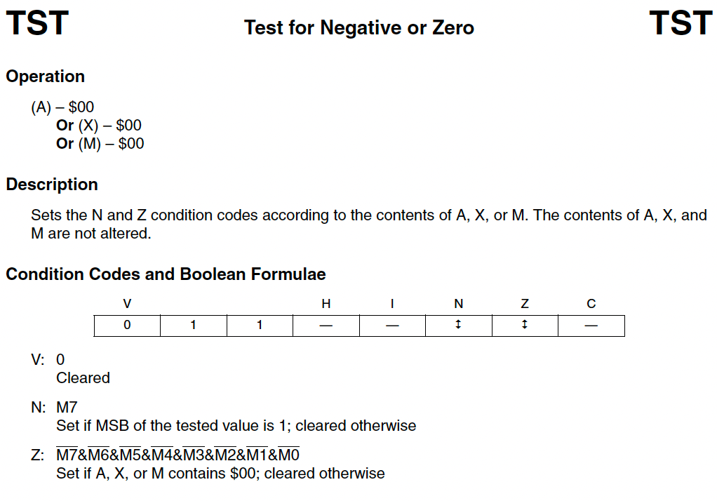
Okay, that confirms my memory and adds detail.
- Z (zero) set if the value tested == 0
- N (negative) Set if MSB is set.
- V (overflow) Cleared
As for the source of the value tested:
- A – accumulator register, the workhorse register for most actions in the CPU.
- X – Lower half of the H:X Index register.
- X is another 8-bit work register.
- H:X in unison can be used for 16 bit addressing into memory.
- M – addressed memory location.
- This can be in RAM, ROM, or system register.
BEQ (Branch If Equal) will jump if j==0. What? Well, any test for equality will set the zero flag. BEQ checks the Z to determine if a jump is required. Where do we jump to? We jump to the label _ILSL_2:at the end of the function. Quite right too; If we are shifting by zero, we are not shifting, and our work is done.
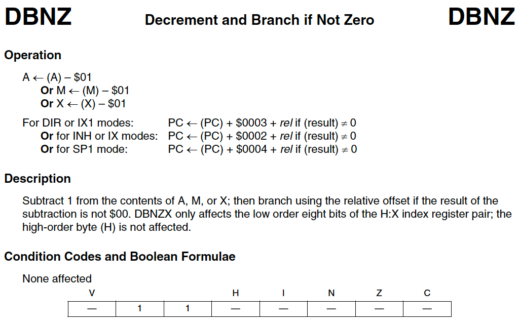
So let’s look at the actual shift. It looks like we are shifting the accumulator (A) and rotating the index register (X). As for DBNZ? I last did Motorola Assembler in the late 1990s. I know it’s something that happens “if not zero”. With a label as a parameter it looks like a branch instruction. Could D be a decrement? I guess we are iterating.
  _ILSL_1:
                LSLA
                ROLX
                DBNZ j,_ILSL_1
I hadn’t noticed there is no parameter being passed to the shift and rotate. We are only moving one bit at a time, so we need to iterate j times.
I am really curious about that rotate, aren’t you? I’d expect both to be shifts. Chapter 6.5.4 gives us the answers.

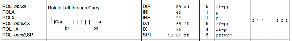
That’s fun. We are actually doing a 9-bit operation on an 8-bit register. The 9th bit is the carry flag. Look at how shift and rotate are similar. This is a logical shift, you will always create a “hole” as you move all the bits left or right, the one that falls off the edge is captured in the carry, and we zero pad the gap made at the other end.
Okay, so we have our value to shift held in a 16-bit register spanning A and X. We do an 8-bit shift on the lower half word in A, anything that falls off to the left gets held in carry. We immediately do a rotate left of the X, this shifts the upper half-word and brings in the carry previously shifted beyond bit-8 of register A into bit-0 of X.
DBNZ will decrement the loop counter j. As we know j will eventually decrement to zero, setting the Z flag. While the Z flag is not set, after the decrement we branch back to our first label, starting the next iteration.
There was a time when I used to write my for loops that way around. Why leave it up to the optimizer? Those days are long gone.
for (j= target_val, j, j--) {...}
Could we extend the shift to 32-bits? I believe so; add a couple more rotates, with some moves in between. Actually the reference manual has this to say on the subject.
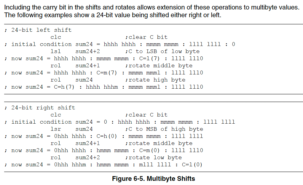
They are using a slightly different form of the LSL and ROL; they are using memory addressed locations. The result is in sum24, which is a “variable”, its actually RAM pointed to by an address, probably set through an RMB (reserve memory byte) in the ds.s data section of RAM. I think the LSR example should be using ROR not ROL; another example of CAPE?
Did we get the answer to our problem? Yes and no. We can see we only have a 16-bit shift for our 32 bit number, so we can explain what happened when we shifted for the 16th time. Our bit fell out of the shift/rotate chain, and became zero.
Where did our big negative come from then?
Implicit Casting, Type Conversion, Sign Extension (The Perils Of C)
At some point the system added some assignments for us. We pass a 32-bit value from our parameter into our shift function. The result of our shift is passed back into the same 32-bit variable location in RAM. You remember asking for that?
Look at the code where we asked for that 32-bit to 16-bit to two 8-bit to 16-bit to 32-bit conversion to happen; it’s pretty opaque.
bit_pattern = 1 << col;
We asked for a 32-bit shift. Well, actually a 16-bit shift, so the compiled code will truncate to a 16-bit integer. Looking closer, I was so in my 32-bit mindset, I never questioned if 1<<col was really going to be treated as 32-bit? Since bit_pattern is a uint32_t I certainly hoped it would be. I was wrong, but know better now.
We saw how the assembly language code took in that 16-bit data into the A and X registers to manipulate. Actually, we saw a comment saying that X and A were loaded from i, but we didn’t see the pertinent LD (load) or MOV (move) instructions or how X and A values might be preserved before the function call to _ILSL. That’s a whole subject in itself.
void _ILSL(char j, ...)
/* DESC:    16 bit shift left k = i << j
   IN:      X:A i, TOS j
   OUT:     X:A k
   WRITTEN: A,X */
We didn’t see how a 16-bit value was passed back into a 32-bit variable. The comment is a terse
OUT: X:A k
That tells us we are writing a 16-bit value, 8-bits from each X and A, into a 32-bit space. That leaves 16 upper bits that we are not copying X:A in to; what happens to them?
Ever heard of sign-extension? Our friend two’s-complement is back. C will happily allow you to copy a value into a variable that can hold a larger data type. If you are using integers, then we have to make sure negative numbers stay negative; likewise, positive balues must remain positive. How do we do this?
We know that if the MSB is set in a signed integer if it is negative. Indeed, all bits above the most significant bit will be a 1 for negative value. For a positive number, all bits above the most significant will be a zero.
Let’s take a simple example of moving an int8_t to an int16_t.
| Value | 8-bit representation | 16-bit representation |
| 1 | 0x01 | 0x0001 |
| 127 | 0x7f | 0x007f |
| -1 | 0xff | 0xffff |
| -128 | 0x80 | 0xff80 |
For whatever reason, the result of our shift got interpreted as a signed value at some point and was sign extended when moved into the final destination.
Our 16th LED, bit-15, is represented by the bit pattern 0x8000. This got sign-extended to 0xffff_8000. That turns on the 16th LED but also the 17th and 18th; the rest of the bits fall outside the range of our LP586x. We have said before we are not populating the 18th LED (there’s not even a pad for it), so we only saw 16 and 17 lit.
Summing Up The Debugging
So there you have it. We had three problems.
- Off by one loop error
- This attempted to light a non-existant LED
- Had no impact other than a longer than expected end of line pause.
- Bad sign extension
- cause upper bits set
- turned on extra LED
- Only used 16-bit shifter
- Eventual overflow caused 0 value.
It all falls on me as I made the mistakes
- Sloppy implicit casting
- Maybe if I used a cast
bit pattern = (uint32_t)(1<<col), it might have used a 32-bit shift.
- Maybe if I used a cast
- poor understanding of underlying shift
- even though I knew I was beyond the 8-bit architecture I still tried this
- lack of
error,info, orwarningfrom build tools.
- Poor review of loop iterators and bounds checking.
The Background Information You Are Missing
So, just to be clear, this is what happens when you (re-)enter the world of 8-bit CPUs. In my case, an S08-based MCU, namely the MC9S08PA32 and MC9S08PA60. These NXP chips are in a family that started in the Freescale days and probably stem from a Motorola series.
I’m using CodeWarrior 11.1, which, though downloaded from NXP, is branded Freescale and is 10 year old now.
The LED driver is a TI component, one of the LP586x family. It supports up to 8 lines of 18 LEDs. The LEDs are manipulated in groups of 18, that is three 8-bit registers in per line in the LP586x register map, they are split into groups [7..0], [15..8], and [17,16]. To quickly accommodate the 18 bits held in 24 bits of register, why not use a 32-bit register?
The hope was that the C shift function would accommodate a wider data type. You can do floating-point math without an FPU (floating-point unit) on board. By analogy, you can sometimes shift more than your shifter permits or your architecture would allow.
When I decided to try the 32-bit bit-pattern I knew I was taking a chance, but it’s easier than manipulating 3 registers independently.
My Solution
I actually had already solved this on the MC9S08PA60 LED panel, where I had 72 columns of LEDs.
I just was adding a quick check on board bring up for the MC9S08PA32 LED panel with its 18 columns. I mean, it’s just a walking-ones test, re-writing one was easier than porting my library that had hardware dependencies in it.
I actually learned some other lessons and incorporated them into this final (for now) version.
void panel_walking_dots(uint16_t dot_time) {
  uint8_t cs;
  uint8_t row, col;
  uint16_t start_address = 0;
  uint8_t bit_pattern;
  for (cs = 0; cs < cs_count; cs++) {

    for (row = 0; row < 7; row++) {
      // Erase row before starting
      panel_write_line_dots(cs, row, 0x00, 0x00, 0x00);
      LP586x_VSYNC_pulse();

      start_address = LED_Dot_Onoff_Register_start + (3 * row);

      // Exercise column 0-7
      for (col = 0; col < 8; col++) {
        bit_pattern = 1 << col;
        LP586x_write_register(cs, start_address, bit_pattern);
        LP586x_VSYNC_pulse();
        delay_ms(dot_time);
      }
      // Turn off all LEDs in 0-7
      LP586x_write_register(cs, start_address, 0x00);

      // Exercise column 8-15
      for (col = 0; col < 8; col++) {
        bit_pattern = 1 << col;
        LP586x_write_register(cs, start_address + 1, bit_pattern);
        LP586x_VSYNC_pulse();
        delay_ms(dot_time);
      }
      // Turn off all LEDs in 8-15
      LP586x_write_register(cs, start_address + 1, 0x00);

      // Exercise column 16-17
      for (col = 0; col < 2; col++) {
        bit_pattern = 1 << col;
        LP586x_write_register(cs, start_address + 2, bit_pattern);
        LP586x_VSYNC_pulse();
        delay_ms(dot_time);
      }
      // Turn off all LEDs in 16-17
      LP586x_write_register(cs, start_address + 2, 0x00);
    }
  }
  LP586x_VSYNC_pulse();
}
Lessons I Learned While Writing This Post
I actually spotted a few things going through this. I finished the debugging Friday morning, capturing for the blog as I went.
While writing this article, I spotted that a cast might have forced a 32-bit shift.
Today was the first time I opened the reference manual to see how I could make my own 32-bit wide shift function. Seeing the rotate-through-carry made me question an issue I had with a Motorola 68HC11 back in 1994, where I could not get the rotate to work, so I made my own.
I was using the 68HC11 to drive a data radio, the single UART port was busy talking to a GPS engine, and I had to bit-bang a serial interface to the radio. To shift the data to the end bit to mask and transmit, I was using a rotate. Of course, after my rotation, I was comparing to a bitmask for the bit to send, then toggling I/O, and then iterating on the next TX bit. That carry bit would long since be dropped. For whatever reason, I wanted to preserve the value in its original location, so young me naively thought I could just do the 8 rotates, and I lost track of how a bit was passing through carry. I guess I assumed that the rotate worked within the 8 bits, and the old bit-7 got latched into both bit-0 and the carry flag at the same time.

That page from the 68HC11 manual shows “Rotate Left” whereas the newer HCS08 boot clearly states “Rotate Left Through Carry”, and adds a clearer illustration of the shift chain.
I’m better at reading datasheets and reference manuals now, but you can also see that the reference manuals have matured a bit.
Wrapping Up
If you made it this far, thank you for sticking with it. I know it got technical, very technical. That’s how firmware gets at times.
I don’t think I see fundamentals, such as a logical shift, tripping up engineers as much in the world of 32-bit CPUs.
I started my career writing assembly language code on a BBC Master and Acorn A500, with a 68020 processor. I soon switched to ARM assembler when Acorn launched the A5000 with an ARM 2 RISC processor. I then moved to a different team where we were using a mix of Motorola 8 and 16-bit devices. With these devices, every byte of RAM was precious. For our applications, every millisecond was crucial. In an environment like that you become very familiar with your HW architecture.
Since then, I have rarely strayed away from 32-bit ARM-based systems with an RTOS on hand (uC/OS, FreeRTOS, Tornado). I get nice SDKs from our vendors, I only have to worry about the internals of the peripherals we intergrate and not so much about the specifics of the MCU or SoC that I’m running on.
Stepping back to small-footprint hardware, I had a brutal reminder of how conscious you have to be of what might be happening under the hood. Working in plain old C, I have to be very precise in my typing and type conversion.
As always, the big reminder is to never assume anything and always RTFM (Read The Manual).
I don’t know what’s going to trip you up, but once a month, something will trip you up, maybe for ten minutes, maybe for ten days. As I said at the beginning, you’re non-techie project manager or product manager might not understand where the hazards are. They would benefit from shadowing you for a while.
You saw that I initially dismissed the problem as a “proto board anomaly,” but I did right to revisit it; there were real code issues.
Fortunately, once I saw the numbers, I understood the boundary condition that caused the two big problems I had. Knowing a single operator in C didn’t necessarily mean a translation to a single opcode; I knew to step into what, on the surface, looks like an atomic (self-contained, single operation, or uninterruptable sequence) function. Someone whose experience is limited to 32-bit machines might not recognize that and stumble for a day or two; for me, it was a few minutes to spot my embarrassing, simple mistake.
Sometimes, we say, “Oh, that’ll be an easy fix,” and defer the deep-dive investigation. Stack those all up for the week before delivery, and you may find one of them is a really nasty bug that costs a week.
I love finding the root cause of a bug.
Have you had any interesting bugs recently?
End Notes
Powers of 2
Powers of two tables are easy enough to find. I grabbed one from Wikipedia.
Idiomatic Languge and Jargon
For inclusive language, you are not meant to use idioms. They can lead to confusion, but without them, a blog post can be a little dry and lacking personality. So I have unashamedly used some.
- Other fish to fry
- An English phrase meaning “more important things to do” or “other priorities to attend to.”
- Roll up my/our sleeves
- An idiom that means “to prepare for hard work or a challenging task.” It conveys getting ready to engage in something that may be difficult, messy, or tedious but necessary.
- Finding Fault
- An idiom that means to criticize someone or something, especially without good reason.
- In this title I used it as a double entendre. I was “finding the fault”, and also “finding fault” in my code.
- Double entendre
- Of french origin, literally means “heard twice”, and figuratively “has two meanings”.
You can see I failed by using an idiom to explain my use of an idiom.
Another issue is jargon. I try to expand TLAs (two/three letter acronyms) in the first usage. The other day, I saw an article on LinkedIn about “FOMOs to avoid.” I didn’t know the acronym, so I watched the video for a definition. The term was used a half dozen times but never defined. I did an on-line search and found it meant “fear of missing out”, the very feeling I had when I didn’t know the word FOMO.
- KimWipes
- A paper tissue used in electronics labs.
- Non-linting.
- anti-static.
- Used for cleaning optics or circuit boards.
- RTFM
- stands for “Read The [Fine] Manual” (or sometimes, another F-word instead of “Fine”).
It’s a bit of techie slang used to encourage someone to refer to the official documentation or manual to understand how something works before asking questions.
It’s often a lighthearted or humorous reminder to look things up, though it can sometimes be used more bluntly, depending on the context!
- stands for “Read The [Fine] Manual” (or sometimes, another F-word instead of “Fine”).
- RTOS
- Real Time Operating System
SO8 versus S08
Yeah, naming is hard.
SO8(ess oh eight) is a package size.S08(ess zero eight – often pronounced ess oh eight) is a processor architecture.
Choose your fonts carefully.
Photo credits
Actually, all the photos are by me. The Susuwatari (soot sprites) pictured are actually made by me, too, and were a gift to a friend who is a fan of Miyazaki.
Further Reading
- HCS08 Family – Reference Manual
- HCS08RMv1/D
- Rev. 2
- 05/2007
- Freescale.com / NXP.com

https://www.facebook.com/rudyrudywangwang/posts/pfbid02CQbtyGF8ZY1W4adqQFXW1UGszWRrskw4tQezzvcfFoM8ftY9M8usreePDa6iDid3l
LikeLike
Sorry – can’t seem to post code block in the comments section.
I can send you the source code via email, from rudywang@yahoo.com
BTW – I’ve only done eye-ball unit testing of the code. 🧐
LikeLike
Thanks, I had thought about using “clock arithmetic,” that is, using modulo.
The problem I had came in the second ground-up writing where I was trying to be “too clever.” My “solution” was a minor rework of my older code, the straightforward (linear) code. I got to a point of diminishing returns, so I moved on.
Another colleague pointed out in a DM how I might have tried `bit_pattern != 1L << bit_position`. I've been looking at other problems, so I have not revisited this recently. I may do some code cleanup. I may look for a definitive answer. Right now, the code is deployed and performing its job within speed and ROM/flash constraints.
LikeLike