Debugging Embedded Systems
Alex O’Donnell
The full hardware interface
When working with two nodes on a bus, it is very easy to focus on the bus in isolation to the rest of the system. It is also very easy to discount other traffic on the bus outside the scope of our connection.
When looking at the interface between two ICs, such as an MCU and a peripheral, the complete interface must be considered. The full interface may include several other signals that are not included in the bus. Common connections between a controller and a peripheral include
- power control
- reset control
- interrupt signal
- write protect
- enable
- chip select
The bus may also be non-trivial. – Bus expander – level shifters – multiple nodes
Your corrupted data packet may come from a bus collision, or a badly enabled device. The problem may be as simple as the peripheral has not been powered, or as complex as bit banging not meeting a timing budget.
The following are examples of what a full interface may entail.
Level shifters
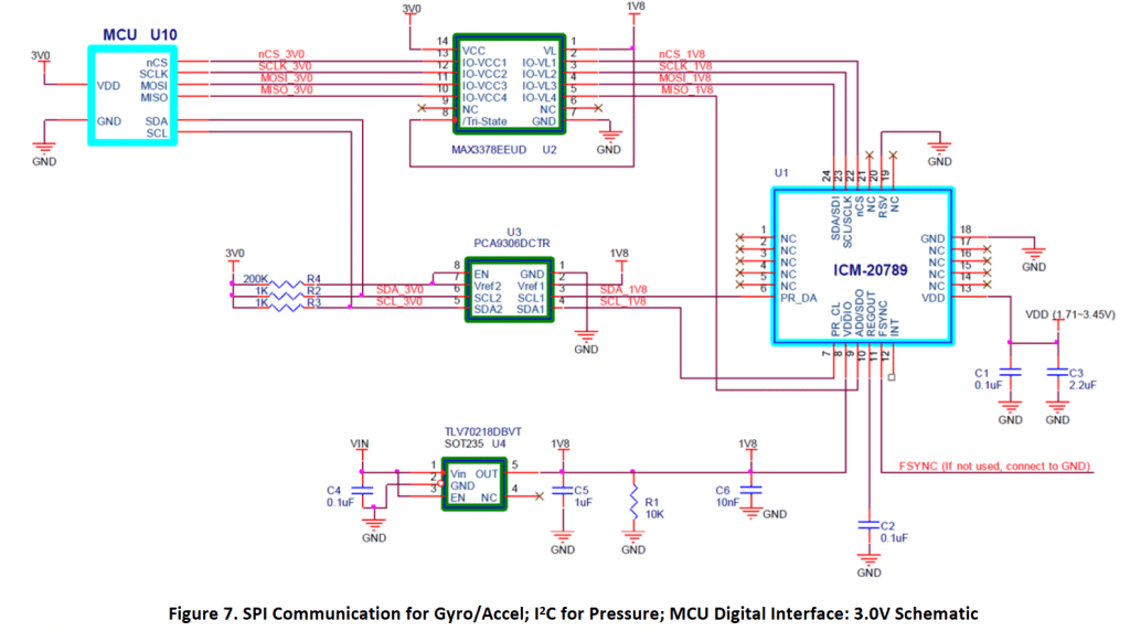
The above shows an MCU operating at 3v, but communicating to an IMU which works at 1.8v. Both the 3V0 and 1V8 power rails need to be powered for the system to work. There is both an I2C and an SPI interface to the IMU.
Write protect
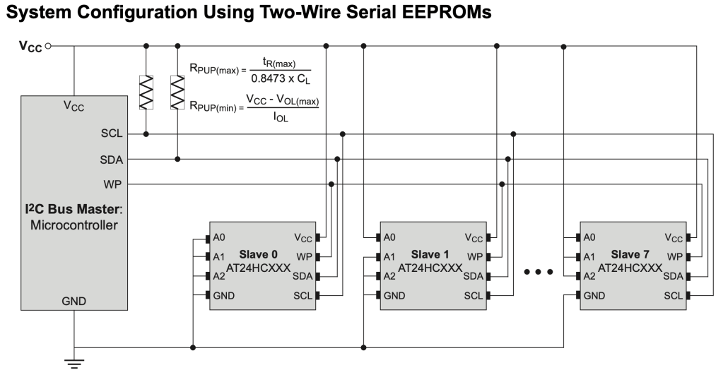
Here we can see three EEPROMs connected to the host controller via TWI. Each device has different connections on A0, A1 and A2 to give unique addresses. There is finally a common write protect signal WP. If the write protect signal is low we can write to all three devices.
Interrupt, reset and bus multiplexing
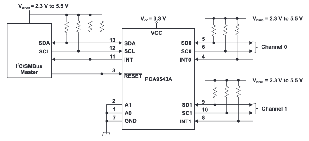
This is a curious device, the PCA9543A from Texas Instruments (TI) is a 1:2 I2C multiplexer (mux). Such a device can be used to reduce bus loads, and allow for repeated addresses of target devices. The mux can reside at one of four address, defined by A0 and A1. Since one use case for the mux is to avoid address conflicts it makes sense that it can have its own address nudged out of harms way.
The mux allows interrupts from the downstream bus to propagate back to the I2C controller. The data sheet states that $\overline{INT0}$ and $\overline{INT1}$ are combined, and not switched, meaning both interrupt sources always get back to the controller. $$ \overline{\text{INT}} = \overline{\text{INT0}} \text{ }\bold{AND} \text{ } \overline{\text{INT1}} $$
To put the mux into its default state a RESET# (active low reset) is present. A device held in reset will be non-responsive. The schematic does not show if the reset is the system reset, or controlled by GPIO from the host controller. If the reset is controlled by GPIO, then we may not get a clean reset if the controller hits an internal reset, or if a push button reset is used. With such a reset to the controller, there is a good chance that through reset the GPIO pin is tri-stated, and the pull-up on RESET# would prevent the mux seeing the reset. The GPIO controlled reset is entirely under software control.
With a multiplexer in the system we have to be sure to set it up appropriately before communicating to downstream devices.
Debugging at the system level
As you are debugging, just remember it is a system. You may be used to opening an socket in software, and any problems are down to message payload issues. In embedded systems your problem may be in one of
- badly configured supporting hardware
- missing power
- un-configured devices
- reset held to a component
- bus conflicts through GPIO state
- two chip selects active concurrently on a SPI or parallel bus
- missing jumper on board
- address select, write strobe
- especially true with prototype boards and eval kits.
- poor re-init/clean-up on shared resource
A protocol problem may actually be fallout from a larger system set up problem. The time to debug at the system level is typically one of these scenarios – new stuff – board bring up – making sure basic functionality exists – driver bring up – first time connecting to a port/interface – integration – turning on all the interfaces – running full system
The time you stay focussed on a narrow protocol debug are – stable board – stable interface driver – update client for a driver – upper level messaging – using new feature within a protocol or IPC (inter process/processor communications) channel
