I have a pet peeve. I often see code where a GPIO (general purpose input/output) pin is set as an output, an then the value is set. I cringe every time I see this in code, and the capture below shows why I don’t like it.
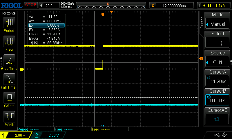
This is my SPI (Serial Peripheral Interface) being monitored. Actually, we are only looking at the CS# (Chip Select – active low) and the SCLK (Serial Clock) trances here.
A text book transaction has a falling edge on CS# to enable or select the peripheral I want to talk to, then some multiple of eight clock edges for bytes of data. To close the transaction we need a rising edge on the CS#.
How do we get such a lovely 11us pulse? Well, we do this by a sillyness in the code.
  //set up chip select pins as outputs as the Arduino API
  //doesn't handle automatically pulling SS low
  pinMode(vspi->pinSS(), OUTPUT); //VSPI SS
  digitalWrite(vspi->pinSS(), HIGH); //pull ss high - not selected
What’s wrong with that? I’ll tell you what’s wrong. If we had looked at the value of pinSS (the old name for CS) we would see that it was LOW before we enabled, and only HIGH after the digitalWrite(). It varies from system to system, but the default is often for a GPIO to default as Hi-z or tri-state or input at the start of time, and the data output register to default to 0 or LOW. You should read the programmers reference or data sheet for your microcontoroller, but in general, this is how it is.
So that accounts for the random rising edge. Why the falling edge?
Chip Select lines often have a pull-up resistor to make sure that during the power-up sequence, the peripheral will not accept noise on the SCLK or PICO (peripheral input, controller output) lines as input. You can use internal pullups in the microcontroller (when available) but these are not always enabled at power up.
I was debugging an issue where the peripheral did not start nicely with a warm start, that is, no power up, but just a microcontroller reset. Adding the pull-up resistor helped keep the CS# in the HIGH or non-selected state when the GPIO pin was not under control. That was when I saw the leading edge during boot became a low-going pulse.
I flipped the digitalWrite() and the pinMode() in my code, and now the first time I see CS# go active is when I actually want to talk to the peripheral.
How risky is this?
In this case, it was benign. Just something that caused a single event capture to trigger prematurely on my scope.
In general, it can cause unwanted behavior. What if the SPI lines were doing double duty? They can be, and in pin-constrained systems, they are often overloaded.
Each edge causes a small amount of RF or EMF emission, creating these glitches often enough you can get noise coupled onto nearby circuits, causing a nightmare debug scenario.
Just take care to keep your code clean. Being proactive in coding and vigilant in code reviews can save you days of head scratching later.
